
Panelization
This document is written for our suppliers to help explain to them how panelization should best be done for Worthington Assembly. Best practices, requirements, etc. This is not a document intended for our customers as we prefer to handle this process ourselves. You worry about your design. We'll worry about how to build them. But if you're curious about things, then feel free to read on.
Maximum Panel Size
Our maximum panel size is 400x450. We don't necessarily want them this large, but this is our limit. Any larger than this and we might not be able to process the board.

Number of PCB's Per Panel
Having a higher number of PCB's per panel can help make production go much quicker. But there needs to be a balance. For an order with a small number of units, having panels be single-up is usually ok if that's the fastest/cheapest way to get the PCB's. But when orders get larger, over 25 pieces, it would be best to really consider making the panels larger in order to improve the assembly process.
If the individual PCB's themselves are large, then a single-up panel may be necessary, regardless of the number of units ordered. For example if the individual PCB is over 200mm then it's likely that it would need to remain a single-up panel. However, if the PCB is under that, and the quantity is sufficient, then putting more PCB's into a panel would be preferred. The following is a chart that explains this well.

Multi-up panel criteria
If the cheapest/fastest way to get PCB's would be to leave the panel as 1-up, then any order under 25 pieces is probably fine to leave as is. Especially if the boards are not very small. Very small boards would likely still end up having multiple PCB's in the panel even in low quantity orders, and this would definitely be preferred.
If the PCB is greater than 200mm then it's likely that the panel would need to remain 1-up.
If the order quantity is greater than 25 pieces and the minimum PCB edge length is less than 140mm then we would definitely want the panel to have more than 1 PCB.
If the order quantity is greater than 60 pieces and the PCB is less than 200mm, we may still want this to be a multi-up panel.

This image helps to define what we refer to as the "Minimum PCB Edge Length"
As always, the panel must still have the 12.7mm frame (or rails) around the edges with 3 fiducials on both sides and 4 tooling holes (see below for details).
Frames
Frames should be added to the panel. The rails of the frame should be 12.7mm wide, which is half of an inch. This can add to the overall cost of the panel but in some (many) cases it is worth it. If we need thousands of boards, then we would like to consider the cost savings of only having rails on two edges rather than all 4 edges. But these would need to be evaluated by us on a case by case basis.
The purpose of a frame around the panel is to make sure that if there are any parts that hang over the edges, they have clearance from machinery, and board support if they are heavy. If we find that there is a board that has a particularly long connector, then we should extend the frame on that edge to be longer to support that extra long connector.
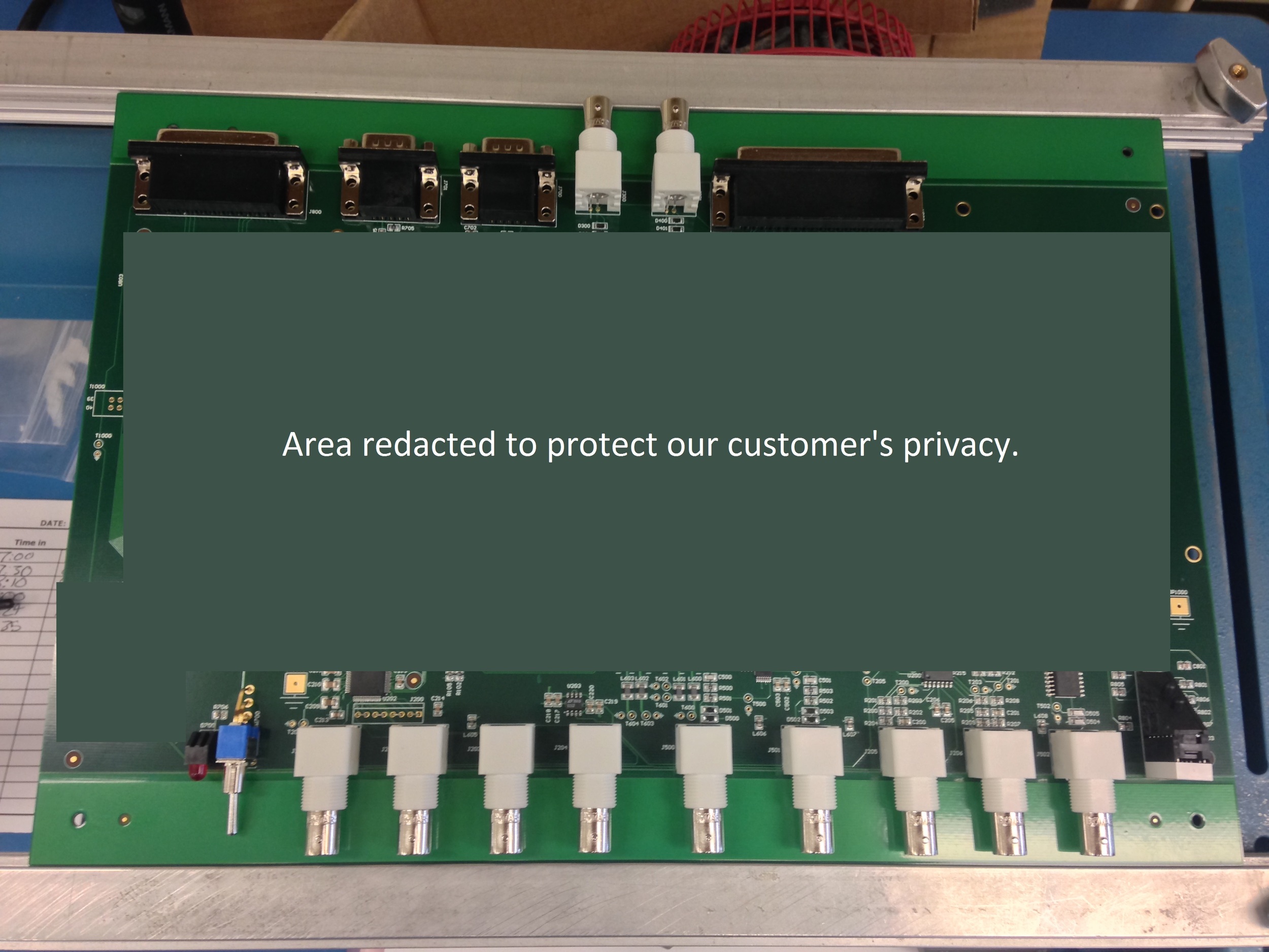
These white connectors are 20mm long. So the rail was made 25mm wide so that the connectors did not hang over the edge of the PCB
The frame also gives the technician something to hold as they are handling the product. Without anything to hold it's easy for fingers to get into solder paste or pre-reflowed, post-placement parts and thus ruin the product.
Frames also enable us to use fixtures in the machinery so that we can hold them down properly. Very thin boards need to be mounted onto a dummy thick board for processing. Without a frame we would have nothing to adhere the tape to for our fixtures.
Rails
In order to save money, we may want just 2 rails instead of a full frame. In other words we will sometimes want rails on 2 sides instead of rails on all 4 sides.
The rails must be a minimum of 12.7mm (or 1/2").
The rails should be on the long edge of the panel. Not the short edge.

This is a bad example. These rails are on the short edge of the panel instead of being on the long edge.

This is a good example. These rails are on the long edge of the panel.
Fiducials
Location
Fiducials should be added to the corners of frames. Ideally, these fiducials would be on the short length of the frame. Meaning, if you had a 171mm x 119mm panel, the fiducials would be on the side of the frame where the short 119mm edge is.

This is because almost all machines grasp the PCB on the long edge of the PCB. Sometimes the tools that grasp the PCB cover the fiducials if they are on the long edge. Putting them on the short edge makes sure that nothing will ever cover those fiducials from view of the camera.
On panels where we only have 2 rails instead of a full frame, we need at least 6mm of clearance from the very edge of the panel to the center of the fiducial. If a rails of 12.7mm is used then putting the fiducial in the center of the rail will be perfect as this will provide 6.35mm of clearance.
Quantity
There should only be 3 fiducials on the panel. Not 2. Not 4. There should be 3 and 3 only.
If there were only 2 fiducials, and you were to put the PCB into the stencil printer upside down (putting the bottom side facing up when you meant to put the top side facing up) the stencil printer would recognize the 2 fiducials and process the board, smearing paste on the wrong side.
If there were 4 fiducials, and they were all symmetrical, but the PCB was not symmetrical, then you could potentially put the PCB in the machines in any direction and the machine would think it has been inserted properly and start assembling them. This is the worst possible scenario.
The fiducials need to be on both top and bottom side. This may seem obvious, but we have had suppliers forget this.
3 fiducials. Only 3. Ever. Period.
Size
Fiducials should be 1mm in diameter with a 2mm masking area. They can be smaller or larger than this if necessary, but this is a good rule of thumb and would be good to standardize on it.

Tooling Holes
Tooling holes, while not as relevant as they used to be, are still valuable to have and don't cost any extra to add. We generally put 4 of them in the corners and make them 3.175mm in diameter (which is 1/8" which was a standard pin support size that most of the industry standardized on in the 80's)


Individual PCB Orientation
Whenever possible all of the PCBs within the panel should be oriented (rotated) the same direction. When PCBs are rotated 180 degrees off from each other it causes a considerable amount of extra work for machine programming. It's especially challenging for our AOI and selective soldering machines. The AOI supports odd rotations but it's time consuming and a rather slogging manual process to get them to work properly. The selective soldering machine just doesn't support them at all. The selective soldering machine just treats the whole panel as one large assembly and can't differentiate them at all, which means the programmer has to program every individual PCB, as opposed to just "stepping and repeating".
But, there are times where rotating the individual PCBs has a great advantage. For instance when there are connectors on one end and by rotating them you can save a considerable amount of PCB real-estate, and thus save a lot of money on the PCB itself. Or if the PCB is an odd geometry and you can get them to fit together well.
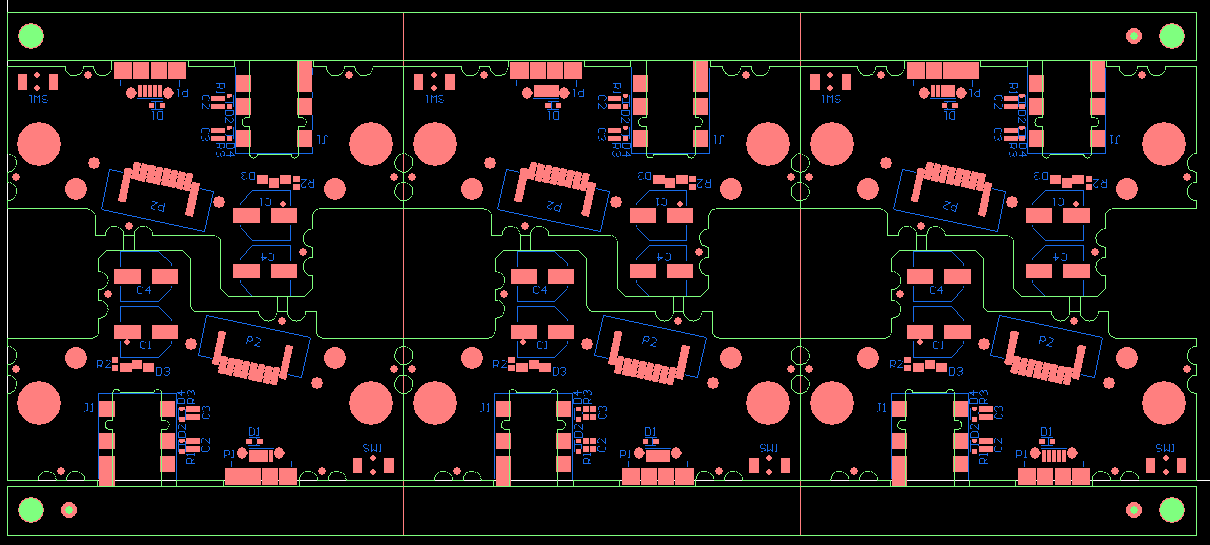
This is a good example of where the odd shape of the PCB made it useful to rotate the individual PCB's within the panel and thus save a lot of overall PCB real-estate

This is a good example where the wifi module would overhang the edge of the PCB so by rotating them you can save a lot of overall PCB real-estate. If you kept them all the same rotation, you'd have to add extra material in between the rows in order to accommodate the wifi module sticking out.
Panel Orientation
All of the panel data should be generated and exported so that the long edge of the panel is on the X-axis and the side with two fiducials is on the lower half of the Y-axis. This is so that we have a standard direction for every PCB we put into our machines and we don't need to think about what direction each individual job gets loaded. We want to make sure we have the long edge with the two fiducials against the fixed rail of the assembly line every single time.

Routing An Area For Overhanging MicroUSB Ports
MicroUSB ports are extremely common in assemblies. They have a flange that dips below the surface of the PCB. So the area where the flange of that MicroUSB port is going to be need to be empty.

You will want to route out an area for relief for this flange. Minimum size for this routing should be 2mm x 10mm. The flange itself is about 1.6mm x 7.8mm so a little extra room is helpful. Typical routing sizes are around 4mm x 15mm and that would be our preference too.

If you have any specific questions about our requirements, notice a typo, or think we are wrong, please let us know. Email the author at cdenney@worthingtonassembly.com or call us at (413) 397-8260